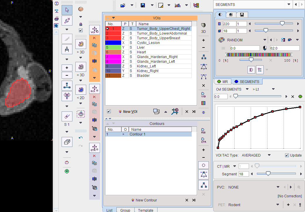
The initial layout of the SEGMENTS panel shown below. The display shows a fusion of the segmentation result (SEGMENTS) with the dynamic INPUT image as the reference.
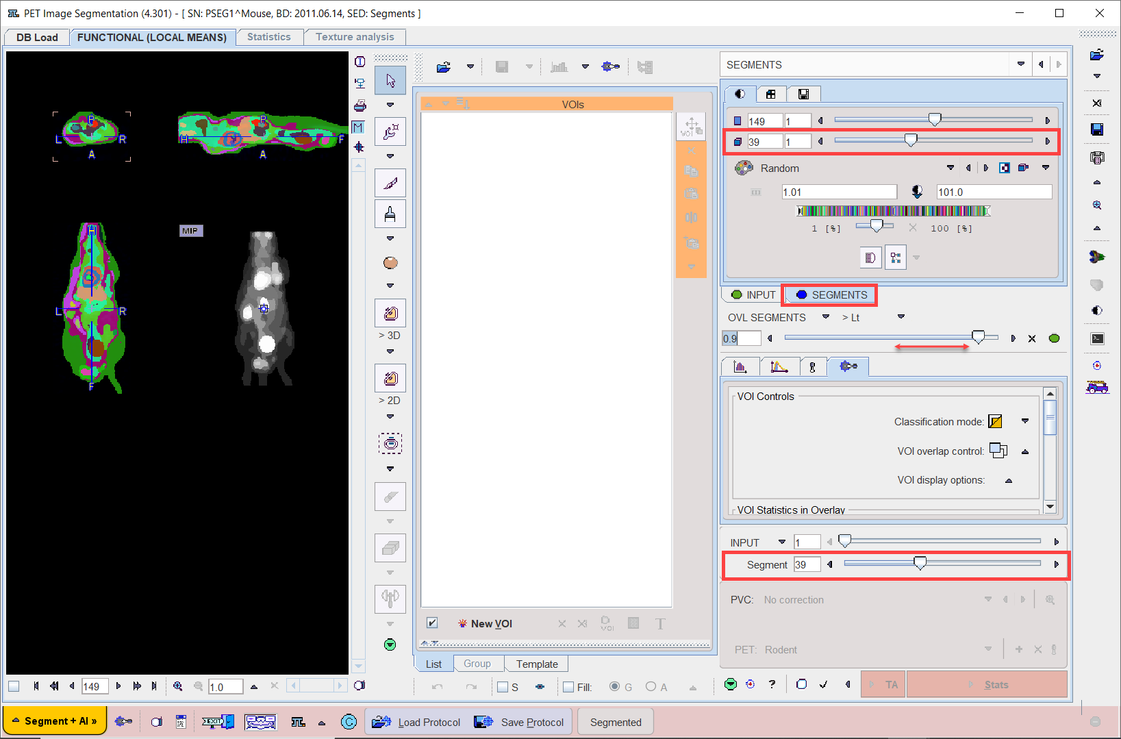
SEGMENTS Image
The FUNCTIONAL (LOCAL MEANS) results in a hierarchy of segments which is organized as a "dynamic" series with increasing number of segments. The first "frame" has only a single segment which corresponds to the whole body mask. The second segment decomposes the area of the body mask into a background and a single segment, the third shows two segments, and so on, as illustrated below.
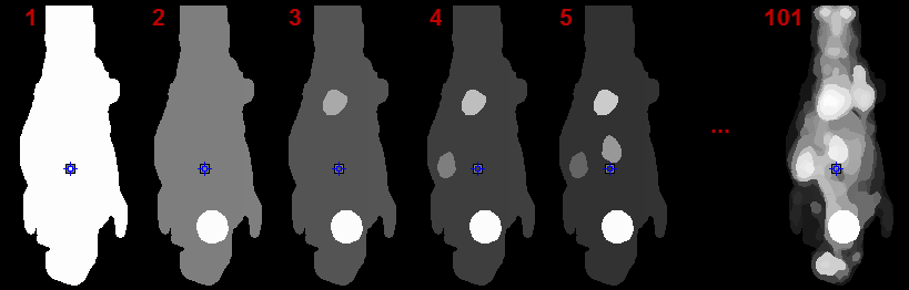
The number of segments can be adjusted by entering the number into indicated fields or dragging the slider. In contrast, the k-means CLUSTER ANALYSIS doesn't provide a hierarchical segmentation, just a single decomposition.
Note: On each hierarchical level, the segments decompose the body mask into disjoint, compact volumes.
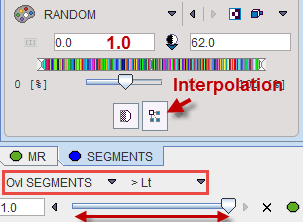
Per default the Random color table is applied for showing the segments decomposition with the aim of separating neighboring segments. Interpolation is switched off to avoid distracting color effects at segment boundaries.
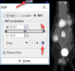
The MIP representation of the SEGMENTS image is a valuable tool for detecting segments of interest. To have it available please make sure the ![]() tab is selected. Furthermore, the full range should be enabled for the MIP.
tab is selected. Furthermore, the full range should be enabled for the MIP.
Reference Image
The reference image which is used as a backdrop for the segments can be selected as illustrated below. The dynamic INPUT as well as the averaged Input (AVR), are always available, and the anatomical images optionally. Note that after switching between the INPUT and anatomical images, the color table most likely requires adjustments.
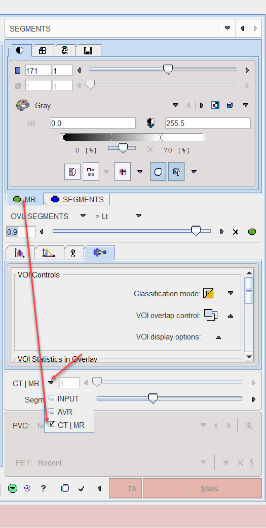
Image Fusion
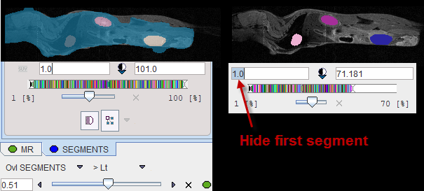
Per default the fusion mode is set to OVL SEGMENTS >Lt, meaning that only the segments above the lower threshold are shown in the image. It may be helpful to set the threshold to 1.0 in order to hide the first "background segment". Please use the blending slider to inspect the reference image below the segments.
Navigational Elements
The number of segments is best changed in the lower right slider area. The recommended procedure is to set the Segment number to 1, and then gradually increase it by the increment arrow.
![]()
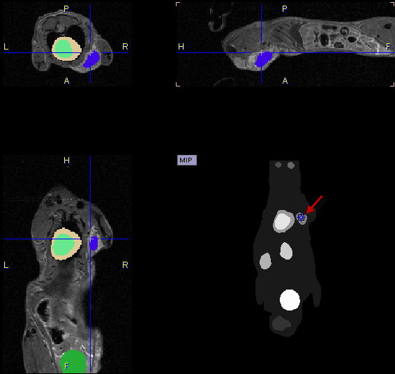
The easiest way to localize segments in the image is via the MIP image: Clicking at a segment will update the orthogonal image planes with intersection at the segment. To center the intersection point on the segment please click on the slice images, or use the mouse wheel for scrolling slices.
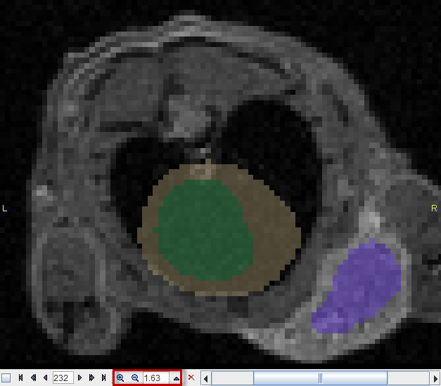
Close examination might require switching the image layout from the orthogonal layout to a single plane layout and some zooming, and then adjusting the blending. There are zooming elements available below the image, but the image can also be zoomed by the mouse wheel when holding down the Ctrl key.
Segment Assignment to VOIs
The basic idea of the whole processing is that the segmentation produces (on some decomposition level) segment definitions which represent meaningful tissue structures in the body. Please use the following procedure for creating a named VOI corresponding to a tissue structure of interest (called "organ" or "lesion" in the following):
1.Select an appropriate reference image wherein the organs can be seen.
2.Adjust the transparency with the fusion slider so that the organ is visible below the segment image.
3.Operate the Segment slider until one of the segments in the image corresponds to the organ.
4.Make sure the ![]() tab is selected. Otherwise the assignment will not work as expected.
tab is selected. Otherwise the assignment will not work as expected.
5.Right click into at the segment in any of the slice images shown (NOT the MIP image).
6.A dialog window opens for defining a name and a color.
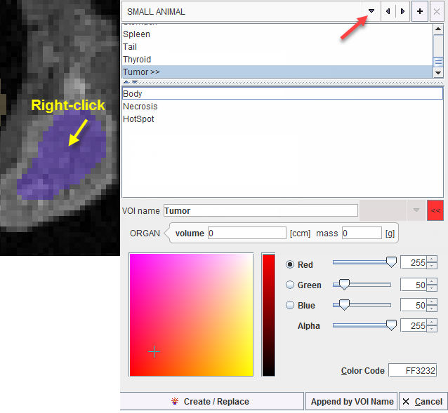
Several lists with pre-defined organ names are available such as DICOM, SMALL ANIMAL and some DOSIMETRY lists. Select either in upper selection. Custom name lists can also be prepared as described below.
7.Select an organ name from the list. Organs with trailing >> such as Tumor>> offer a substructure list. Other organs like the Kidneys offer a Laterality choice. Select as appropriate.
8.The VOI name shown in the text entry field is composed from the selections, but can be edited or completely redefined.
9.Change the VOI color.
10.Confirm the dialog window with one of the buttons. Create/Replace adds the VOI to the list, and overwrites any VOI with the same name. Append by VOI name causes the current VOI to be merged with an existing VOI of the same name. Cancel discards the definition.
The VOI name appears in the VOIs list, the contours are shown in the image, and the time-activity curve is calculated.
Please repeat the sequence above for all organs and lesions of interest.
Custom VOI Name List
A VOIs list with manually edited names can easily be converted into a custom name list: Right click into any segment to open the assignment window. Activate the + button, specify a list name in the appearing dialog window and confirm the dialog window with ok.
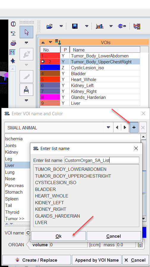
From then on, this list can be used alternatively to the pre-defined lists.
VOI Adjustments and Addition
The VOIs created by segment assignment are regular PMOD contour VOIs which can be adjusted in many ways. For instance, if the segmentation produced two complementary parts of a structure, their VOIs can easily be merged into a single VOI.
VOIs can also be added in a completely manual manner. In the example data set, for example, there is a bright part in the MR image which does not take up FDG.
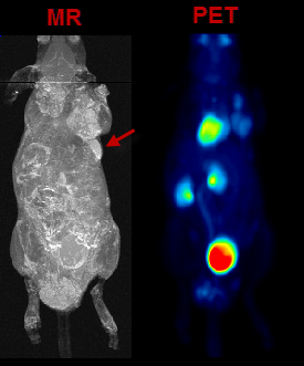
In the present situation, a VOI can be obtained from the MRI image as illustrated below. First, the MR image tab is selected to direct the contouring operation to the MR image content, not the SEGMENTS. Then, a sphere object is placed for enclosing the lesion.
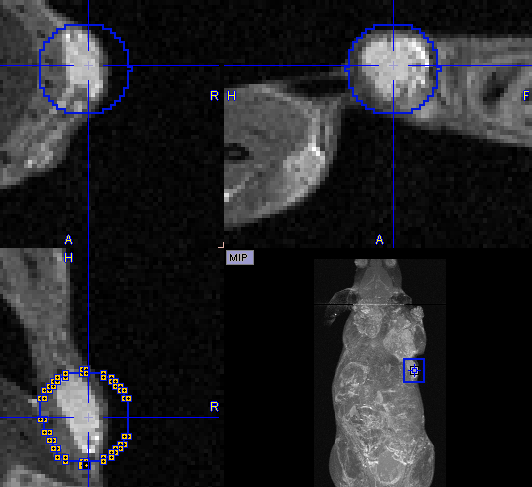
Next, the iso-contouring is started. The parameters are set to 3D with Multi regions off to create a single compact VOI. The iso-contour is shown in the image, and the contouring level may be adjusted by the Value setting.
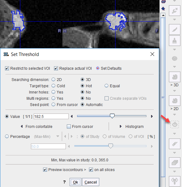
After closing the dialog window with Ok, the contouring result is shown, and the VOI can be labeled.
Morphological Operations
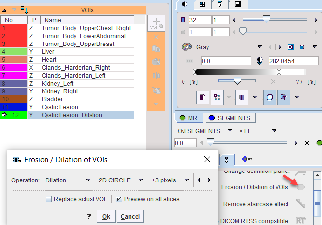
Morphological operations support convenient functions for modifying the created VOIs, such as shrinking, growing, removing holes and single pixels. Please select the VOI to be modified in the list, then activate the Erosion/Dilation function from the VOI tools area. A dialog window appears offering a list of Methods with corresponding Structuring Elements and their size. The changes to the VOI are immediately reflected when configuring the operation. Note that the result may replace the existing VOI, or be added as a new VOI.
Non-overlapping of VOIs
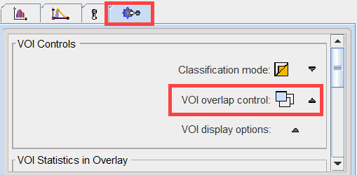
In order to avoid the creation of overlapping of VOIs (which causes problems with partial-volume correction), the VOI overlap control is pre-configured accordingly.
If VOIs are created by the merging of existing VOIs, please make sure that the original VOIs are removed.
Digimouse Visualization
During the assignment of segments to organs it may be helpful to relate the information in the image display with an anatomical whole-body mouse atlas. The PSEG tool includes a 3D rendering of the Digimouse Atlas [1,2] which is only available if the PMOD license contains the P3D rendering option. In this case the corresponding ![]() button in the lateral taskbar is active and launches the tool as illustrated below.
button in the lateral taskbar is active and launches the tool as illustrated below.
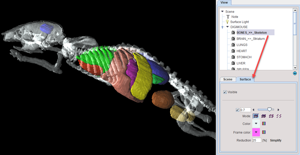
Note the organ list in the View panel to the right which allows selecting individual objects and changing their representation. In the example above, the BONES object is selected, with the corresponding Surface panel giving access to its properties. For instance, by removing the Visible check the bones could be hidden from the rendering. Note that multiple objects can be selected and a property such as transparency changed for all of them at once. Please refer to the PMOD 3D Rendering Tool Guide for more information about the renderings options.
Note: The 3D Digimouse window can remain open while assigning the segments. After hiding irrelevant structures it is recommended to reduce the window size and hide the control area with the ![]() button in the lateral taskbar.
button in the lateral taskbar.
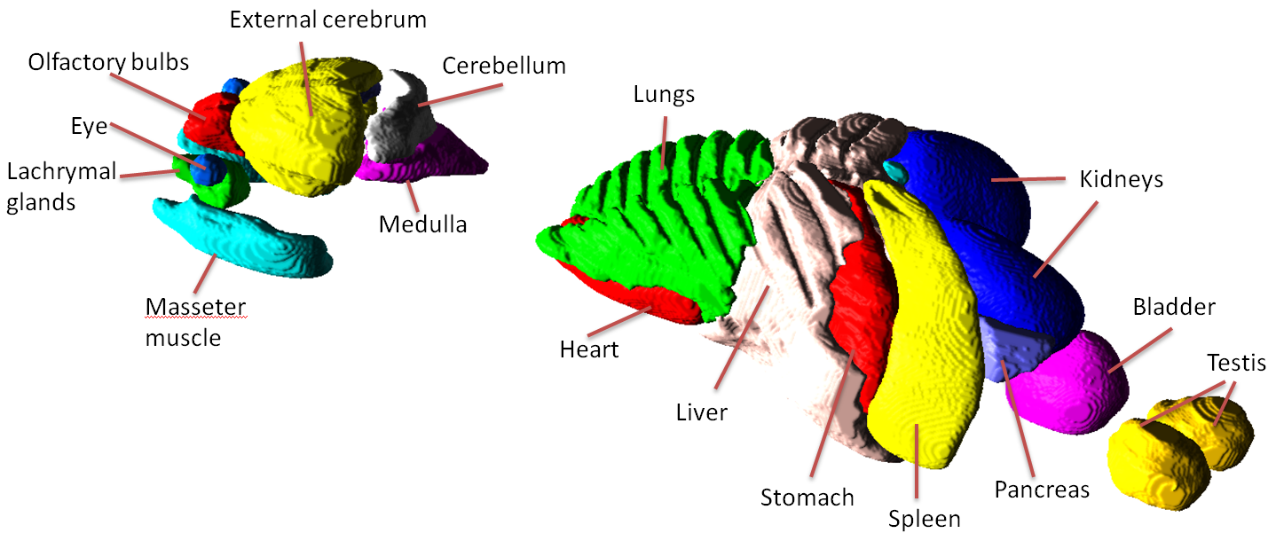
The structures available in the Digimouse phantom are illustrated below.
References
1.B. Dogdas, D. Stout, A. Chatziioannou, RM Leahy, Digimouse: A 3D Whole Body Mouse Atlas from CT and Cryosection Data, Phys. Med. Bio, 52: 577-587, 2007. http://dx.doi.org/10.1088%2F0031-9155%2F52%2F3%2F003
2.D. Stout, P. Chow, R. Silverman, R. M. Leahy, X. Lewis, S. Gambhir, A. Chatziioannou, Creating a whole body digital mouse atlas with PET, CT and cryosection images, Molecular Imaging and Biology.2002; 4(4): S27